A year ago, mostly during a long transatlantic flight, I wrote a simulator for a piece of cloth in TypeScript. In this post I’ll explain how the interesting bits there work. But first and foremost, let’s start with a demo!
Demo
You can interact with the cloth by moving the mouse, and tear the cloth by clicking the mouse button. Click here to toggle debug mode.
Representing the Cloth
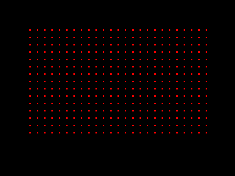
The cloth is represented by a 2 dimensional array of joints, interconnected by springs, representing the strands of the fabric, and allowing the cloth to deform and stretch.
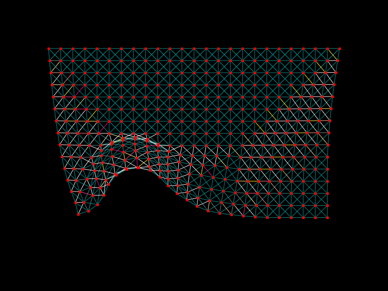
You can see the joints here:
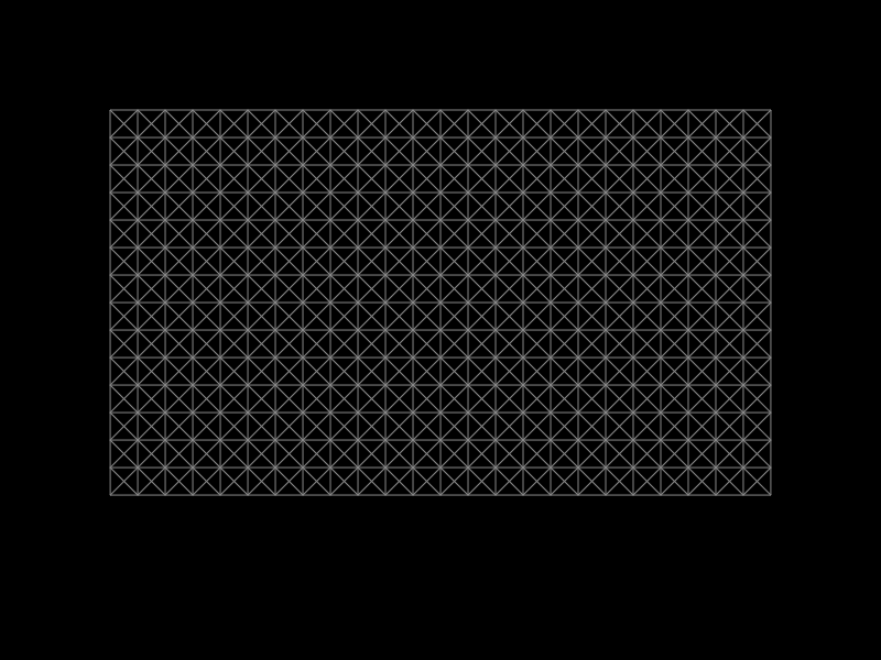
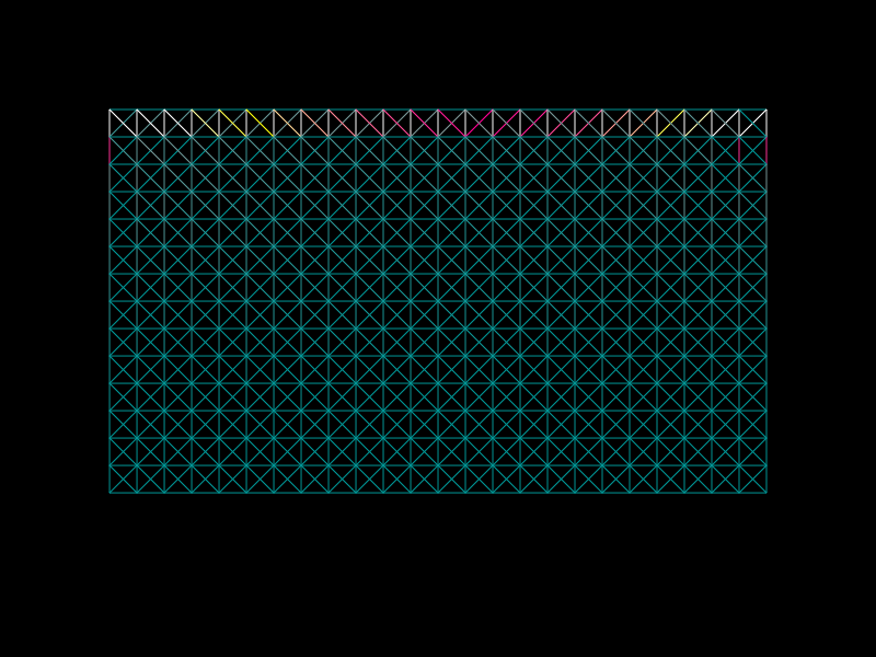
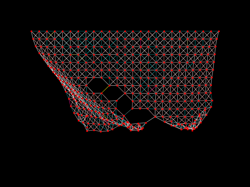
The springs are connecting each joint to its 8 neighbors (up, down, left, right, and up-left, up-right, bottom-left, and bottom-right):
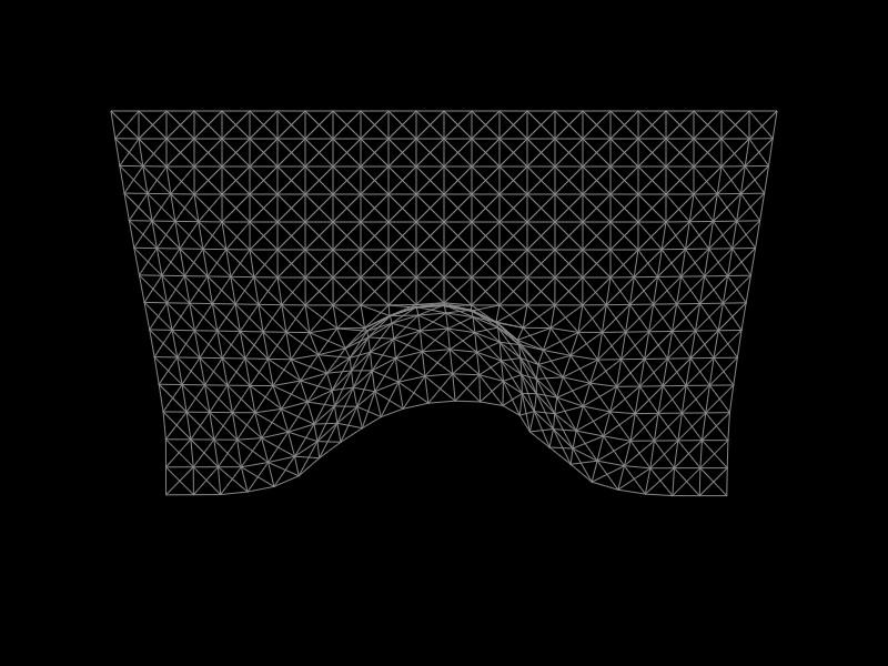
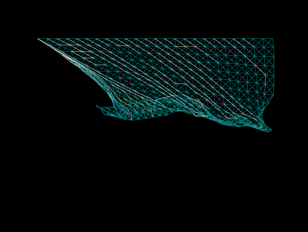
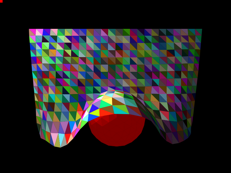
Remarkably, this seemingly simple setup is all that you need, and it already looks like a piece of cloth when we apply more forces. Here are the springs when resting on an invisible sphere:
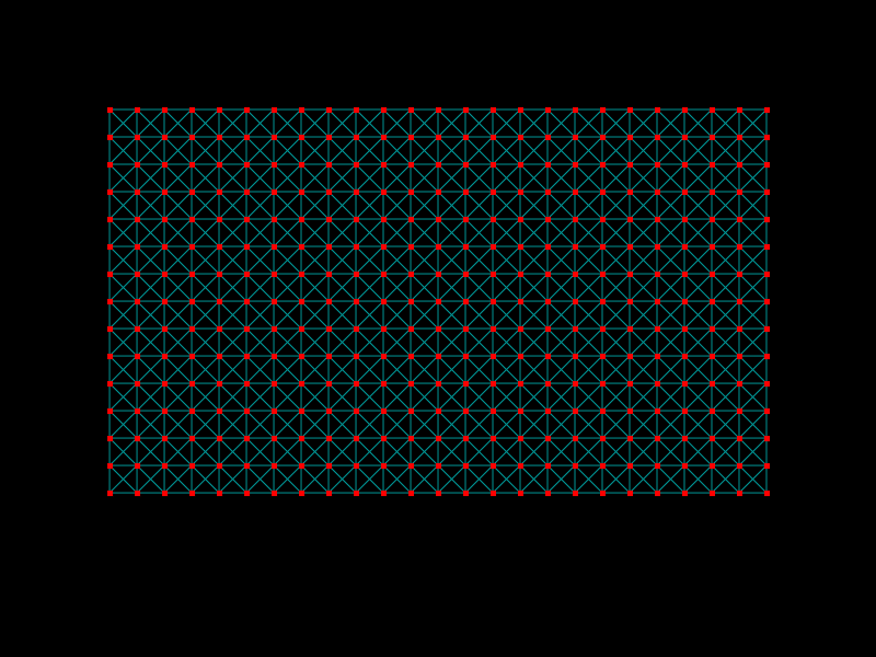
Here are the joints and the springs together:
I experimented with connecting every joint to only 6 of its neighbors (the 4-connected left, right, top, and bottom, as well as the top-left and bottom-right neighbors). This makes the cloth (with the existing parameters) more brittle, while the current 8-neighbor setting, makes the cloth much more stiff.
The joints are simulated as a particle system, where each joint is affected by the forces from the springs, gravity, and the wind.
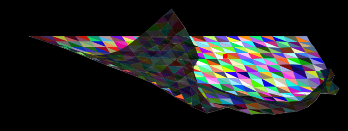
Each spring has some tension that increases linearly with the length of the string, but only in 1 direction (i.e. if the string is longer than resting length it exerts a linear forces towards resting length, but if the spring is shorter than resting length, there is no force pushing it back towards resting length). Here we see the tension during rest (caused by gravity):
Here we can see the tension when an additional force (wind) is applied to the system:
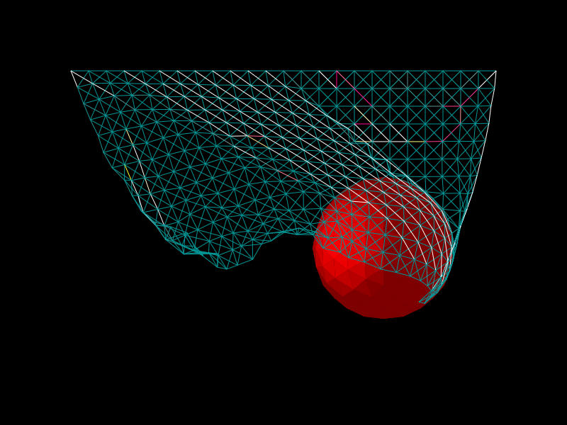
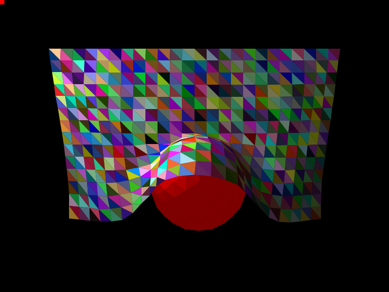
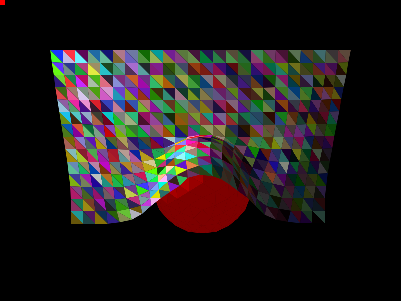
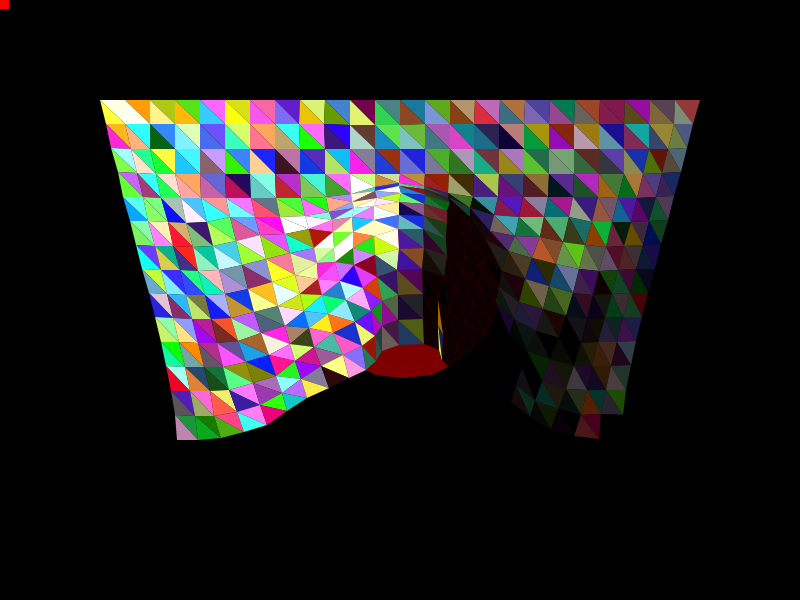
Here we see the tension when the cloth is resting on a sphere:
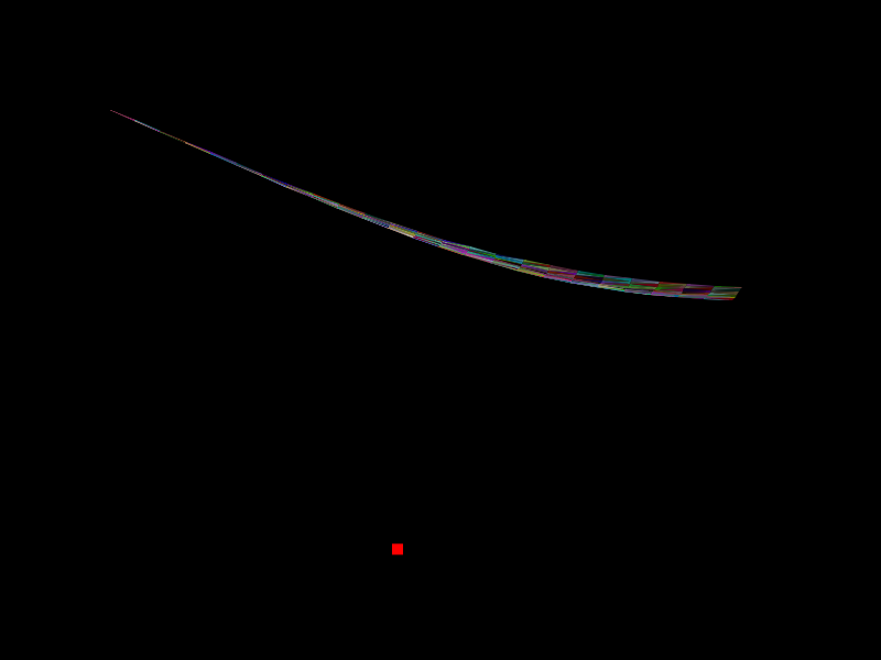
And when the sphere is moving:
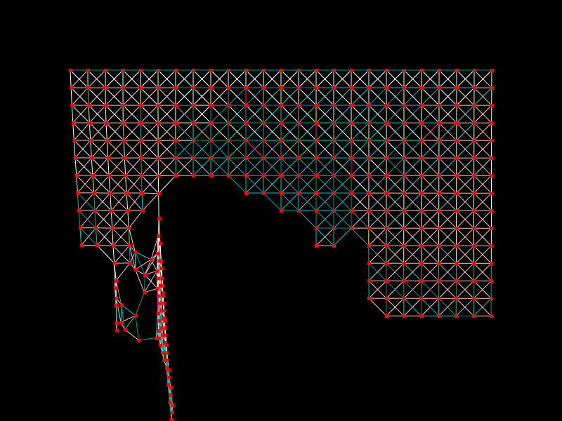
I gave each of the springs a maximum stretch factor, and if it stretches more than that, it would tear:
Verlet Integration
At the core of my physics engine is a function that advances the state of the world. My initial implementation for that function consisted of simply applying Newton’s laws of motion directly (the initial conditions are given by \(x_0, v_0\)):
\[a_{n} = \sum_{F \in \text{forces}} F\\ v_{n+1} = v_n + a_n \Delta t\\ x_{n+1} = x_n + v_n \Delta t\]This resulted in large numerical instability. Instead, I changed my implementation to use Verlet Integration which looks like this:
\[a_{n} = \sum_{F \in \text{forces}} F\\ x_1 = x_0 + v_0 \Delta t + \frac{1}{2}a_1\Delta t^2\\ x_{n+2} = 2 x_{n+1} - x_n + a_1\Delta t^2\]This basically means that instead of maintaining the velocity explicitly, we derive the velocity from the current position and the previous position. This made the physics simulation much more stable. This is a really interesting phenomenon and I’ll probably elaborate about this in a future post.
UIValue
As I was iterating on the numerical physics constants, I wanted a UI mechanism that will allow me to interactively change the values of all such constants (e.g. the wind speed, gravity, radius of the sphere, etc.). HTML makes it extremely easy to build UIs, but I had one interesting requirement: I wanted to be able to decide anywhere in the code (e.g. deep in the physics integration code) that I wanted to have a constant be changeable from the UI, and with a trivial local change, get a UI widget to control that value. I.e. I didn’t want to have a centralized pool of UI widgets, and needing to touch a central registry for every change, etc.
For this purpose I created the UIValue class. It is used like so:
// UIValue(
//   name:string,
//   initial_value:number,
//   min:number,
//   max:number,
//   step:number=1) : number;
let some_number = UIValue("name", 0, 0, 100, 10);
Here is an actual example from the project:
this.wind.x = Math.sin(this.elapsed_time * UIValue("wind_freq", 0.3, 0.1, 10, 0.1)) * UIValue("wind_mag", 0, 0, 160, 40);
This results in UI sliders being created:
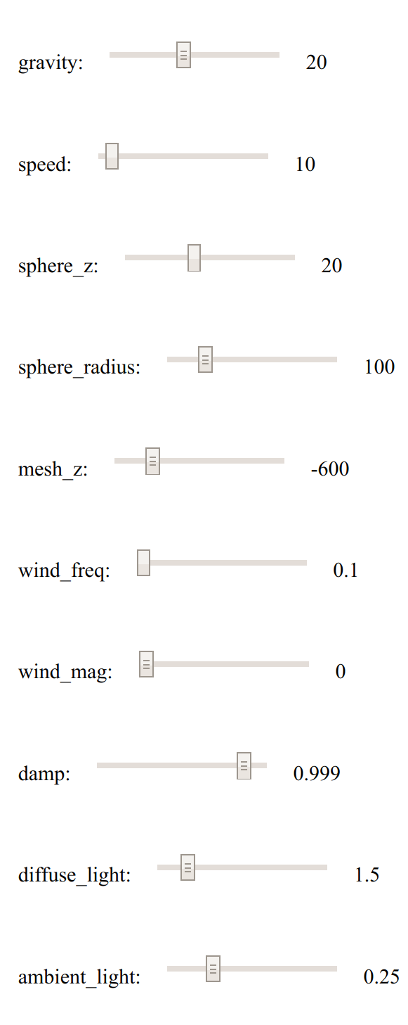
So from the calling code, this is treated exactly like a regular JavaScript number. The slider is created the first time that the UIValue is accessed. Note that the code for the demo above is still full of these, but I turned on a global setting that hides all of the UI widgets and just uses the initial values for the purposes of this post.
There are of course some negatives to not having a centralized location. For example, different code pieces can access the same UIValue, and each of them needs to repeat all of the parameters (the UIValue class does automatically make sure that at least they are always equal, to avoid bugs, incurring a slight performance cost). Another disadvantage is that it’s hard to control the order of the sliders in the UI. But all that said, I was very happy with this mechanism that allowed me super fast iterations.
Rendering
Projection
For this project I created my own rasterization renderer. Everything (the cloth, the sphere) is a mesh, whose vertices are all transformed and then projected on to the screen. I originally implemented perspective projection, but later decided that this actually looks nicer with an orthographic projection, so that’s what’s happening in the demo above.
Here we see a scene with perspective projection enabled:
Here I exaggerated the effect:
And here we see orthographic projection:
Lighting
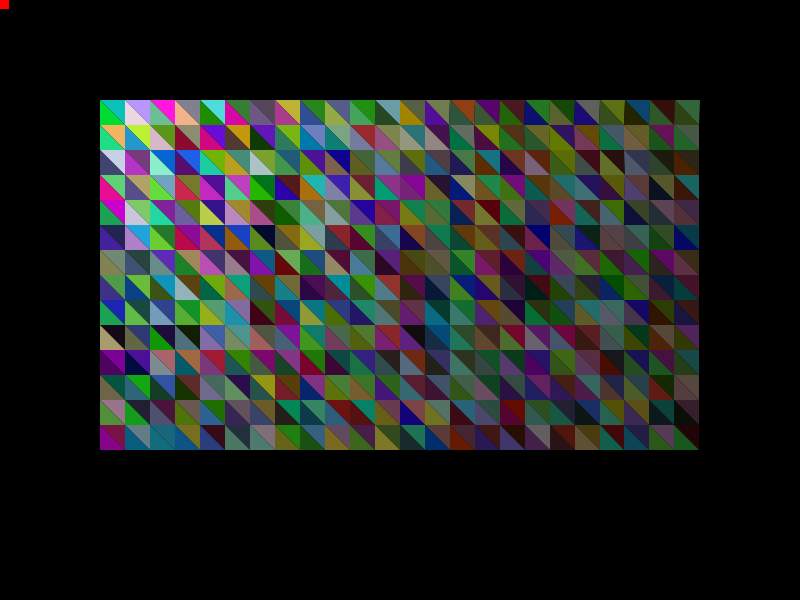
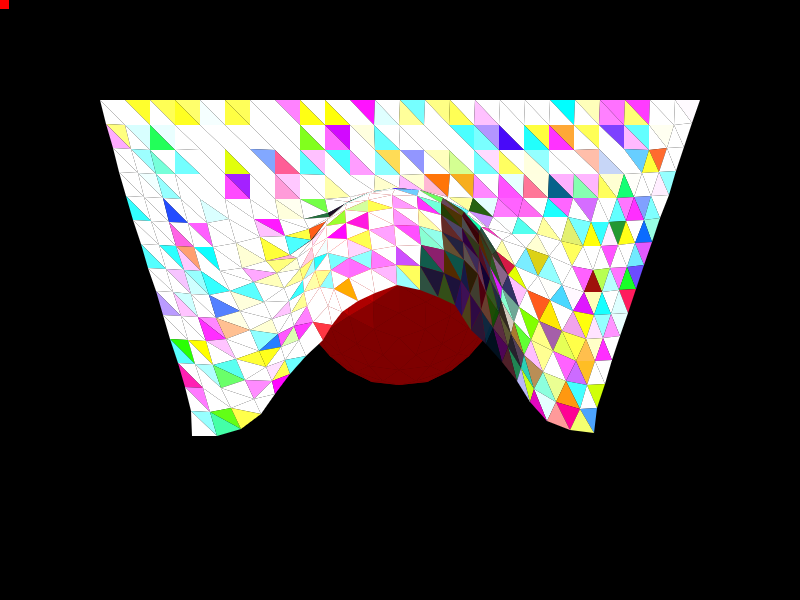
I implemented a simple lightning model, supporting just ambient and diffuse lightning. Here is the cloth with just ambient lightning on:
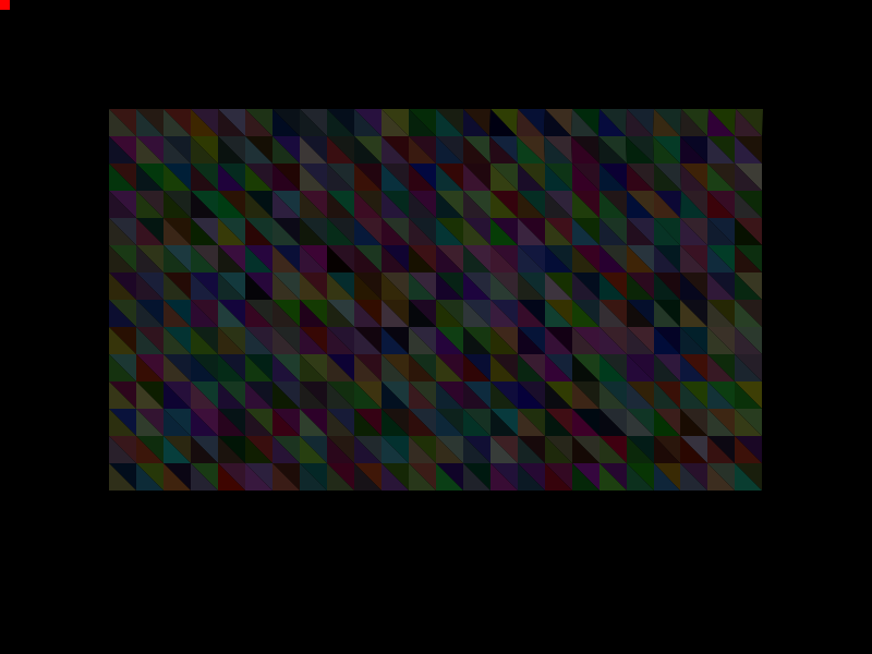
Here is the same scene with just diffuse lightning on:
Here is a version with exaggerated diffuse lightning, without ambient light, to illustrate the difference:
And finally here’s a version with even more diffuse light and some ambient light:
Triangulating the Sphere
Another interesting aspect of this project was rendering the red sphere. While I am using a true sphere for the physics calculations (it is much easier to have my vertices collide with a true sphere than a polygonal mesh), since my engine for this project was rasterization based, I needed some way to approximate a sphere with triangles. What I ended up doing (and produced the best results) was to create an icosahedron and tesselate it. I really tried to avoid this though (I didn’t have connection on the flight and writing the equations for the vertices of the icosahedron was not trivial). My idea was to take any simple shape (a pyramid or a cube) for which calculating the positions of the vertices is trivial, and repeatedly subdivide the faces and normalize the vertices.
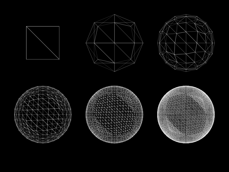
This is better illustrated with some images. Here is a pyramid whose faces I repeatedly subdivided without normalization:
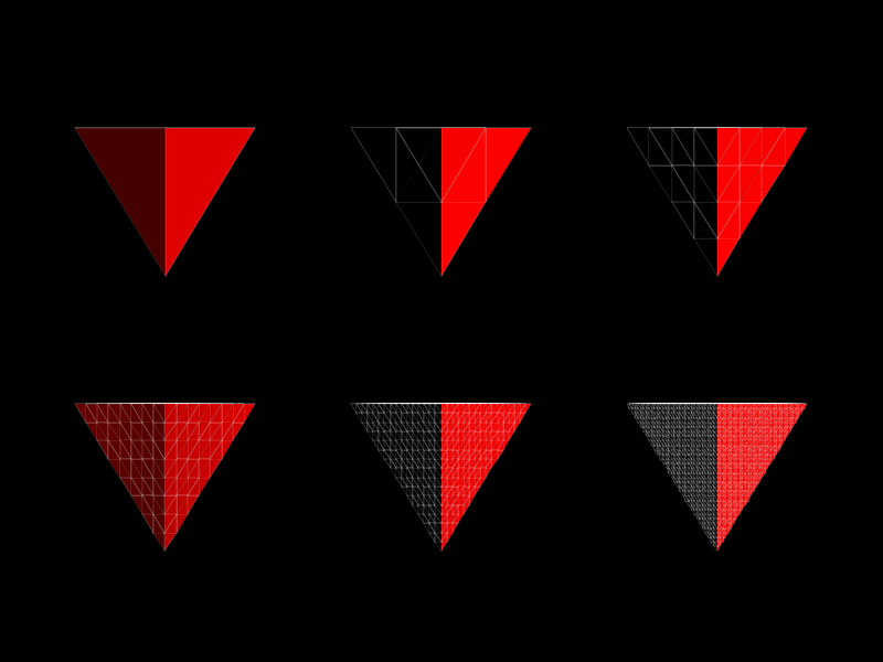
And here it is after normalization:
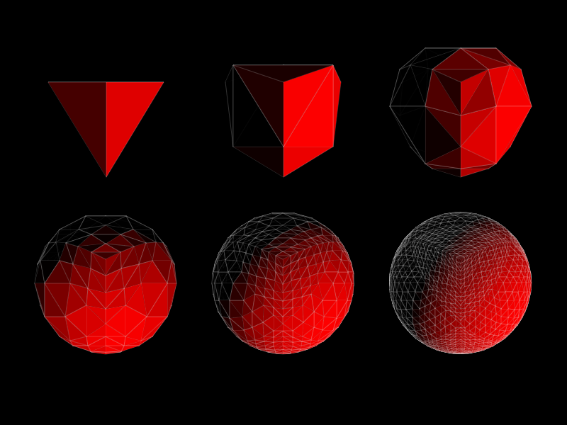
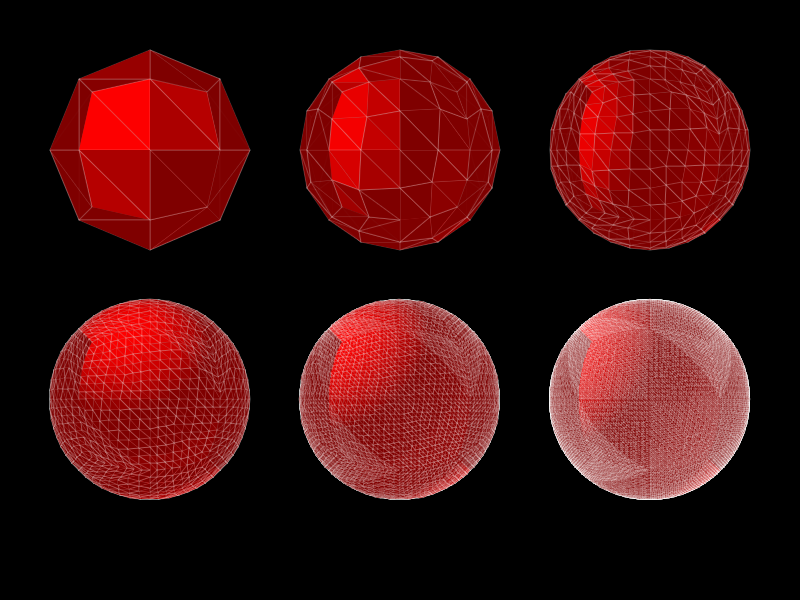
It definitely looks “spherish”, but not perfect. I tried the same with a cube, which looks better, but still not great:
And with the faces lit:
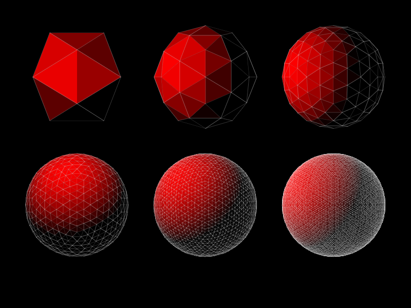
Both of these are ok, but not great, and I finally decided to do the hard work and parametrize the icosahedron:
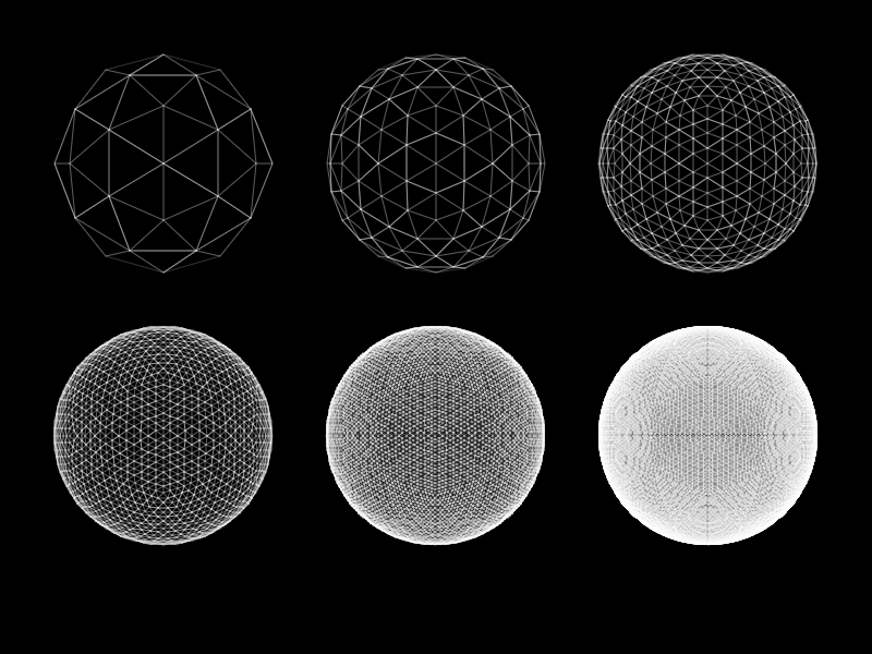
Here it is in all of its regular glory:
Some other elements I experimented with are adding more forces (like wind):
Or changing the point of view:
Hope you enjoyed! See you next time!